

ASK ANDY – our GLOBEClaritas expert!
Q. Can I improve spatial sampling on low fold vintage datasets?
A. Yes, you can, we have dedicated modules that provide robust solutions for up sampling in the shot and receiver domain.
One of the challenges with older legacy seismic datasets can be the comparatively poor sampling in these domains compared to modern acquisition. However, there is still a lot of value that can be extracted from these vintage datasets with suitable processing. Improving the spatial sampling in shot and receiver domain provides significant improvement on sparsely sampled datasets.
We take a two-stage approach to improving the spatial sampling
Stage 1
The example was acquired in 1974, and had a shot fold of 24, with a receiver interval of 100 metres, and as can be seen from the shot record displayed below, has significant aliasing issues which are particularly apparent in the FK plot also shown:
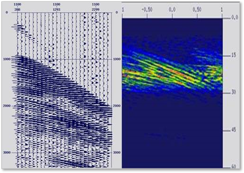
With the current receiver interval, unwanted signal like the direct arrivals, wrap around in the FK domain at around 15Hz. This, therefore, obscures the desired signal, and the aliasing makes it impossible to remove in the FK or Tau-P domain.
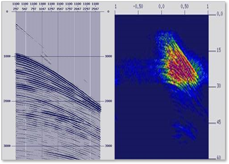
We can however use the OFFREG module to interpolate from the sparse 24 fold, 100 metre increment input gather to a 96 fold, 25 metre increment output gather – the interpolation in OFFREG can be performed in the Time or Frequency domain and uses a least squares polynomial fit solution. To optimize the interpolation we can apply a simple constant velocity NMO correction to the data within OFFREG, usually we select a velocity that over corrects the primaries like the Waterbottom and its associated multiples and under corrects the remaining primary reflectors. You are trying to unwrap the Aliasing so that the interpolator can do its job properly, typically NMO corrections of 1800 to 1900 M/S work well with most datasets.
The resulting Shot gather and FK Spectra (Below) show how the interpolation has unwrapped the aliasing and improved the signal to noise ratio of the data, which will improve subsequent processing steps like SRME/Tau-P processing and Pre-Stack Imaging steps:
Stage 2
Finally, we look to improve the sampling further by reducing the shotpoint interval from the 100 metre acquisition interval to 25 metres. If we left the SP interval as acquired, then our CDP gathers would remain low fold – although we would have more of them.
The acquisition geometry provides for 2 CDP’s per SP and a fold of 12, with the OFFREG interpolation only, we would get four times as many CDP’s at 8 per SP, but the fold would remain 12, making velocity analysis challenging, preserve aliasing issues in the CDP domain, and PRT Demultiple and other processes more difficult.
In the example below, by interpolating SP’s between the existing acquired locations to better sample the data we can use the SHOTINT module generating 4 output SP’s for every input gather. With SP interval of 25 Metres, this results in 4 CDP’s per SP, and a CDP fold of 60, providing better sampling in the CDP domain and allowing for improved velocity analysis and PRT-Demultiple.
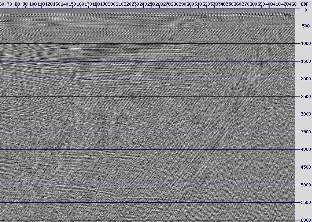
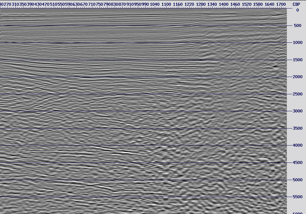
Example job flows using SHOTINT and OFFREG can be found in the Advanced Marine Tutorial available from the Petrosys client Portal. Below we show stacks before and after OFFREG and SHOTINT:
Stack Before:
Stack After:
To find out more about GLOBEClaritas or if you have a question you would like featured in our next Ask Andy please get in touch below.
GLOBEClaritas Enquiries
If you would like to know more or have questions please use the form to get in touch with one of our experts.